During mine shaft construction designers, engineers and operational staff manage vast amounts of technical and spatial data. Our user-friendly tools provide substantial benefits including access to this data, as well as evaluation and forecasting capabilities during various stages of shaft sinking.
The solution offered by Sight Power significantly increases the efficiency of the entire construction process and helps reduce risks during the design, construction and sinking stages. Our software has been developed consulting with mining experts to ensure an accurate and reliable solution.
Shaft Builder is designed to resolve problems during the shaft sinking process. Shaft Builder can be used in combination with our other solutions for mining and geology which provide analytical and visual tools for processing geological, geotechnical and geophysical data in the areas designated for shaft sinking.
Shaft Builder incorporates unique tools for making informed decisions during the most important stages of construction of a mine shaft including:
- The preparation of rock mass for shaft sinking by means of ground freezing.
- Lashing and installations of rock support and shaft lining.
- Ground thawing and rock grouting.
- The shaft equipping phase.
The delivery of various Shaft Builder components may vary and is dependent on the requirements of a particular shaft sinking project.
Shaft Builder includes the following basic features:
Modeling of freezing and thawing of rock mass around the designed shaft
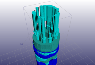
Ground freezing, along with rock cementation and grouting, is a necessary part of most shaft sinking projects. Ground freezing and/or rock grouting are used to prevent shaft flooding during the sinking stage.
The dynamics of the ground freezing process is critically important for project success. Properly executed freezing significantly influences the effectiveness of the sinking phase, whereas “under-frozen” or “over-frozen” rock mass creates substantial problems for the sinking contractors during the next phases of shaft construction.
Freezing the rock mass around a shaft too quickly (to start rock hoisting earlier) may lead to the incomplete establishment of an ice wall with the required thickness at certain depth intervals causing substantial water leakage during sinking. Another extreme is excessive freezing which leads to avoidable power consumption and technical difficulties, delaying the start date of full capacity operations. Therefore, it is highly recommended the process of an ice wall formation is controlled to obtain a significant financial gain.
The freezing process is carried out by the permanent circulation of special cooling agents (brines) in freezing boreholes, arranged in a circular pattern located beyond the boundaries of a sinking zone.
The speed of freezing depends on the mineralogical composition of the rock formations, and particularly their moisture content and salinity. Aquifers typically take longer to freeze than the less water saturated horizons since water has much higher heat capacity in comparison to solid rock.
Engineers make approximate and empirical predictions of process dynamics prior to the start of freezing. The success or failure of those predictions can be checked by periodic temperature monitoring at different depths in specifically drilled boreholes.
The technology offered as a module in the Shaft Builder solution enables mining engineers involved in the design and/or sinking of the mine shaft to obtain highly accurate and reliable estimates of the dynamics of ice wall formation. The model is based on the resolution of the crystallization process and allows users to calculate the ice wall status and thickness at any required date for each geological layer. The design engineer can also conduct “what-if” scenarios by changing the parameters of the freezing process (cooling agent temperature, location of freezing bore holes, turning off and on particular boreholes), and also calibrate the model (to refine the geotechnical parameters) using actual measurements in the monitoring boreholes.
Shaft Builder ensures that the freezing process is well-planned and controlled.
Ground thawing is the process inverse to ground freezing. Thawing operations start immediately after completion of sinking through the deepest aquifer and reaching the impermeable rocks. Thawing can be natural or induced when a warm solution is poured into “freezing” boreholes. Shaft Builder includes a special module for thawing process simulation with an additional optimization tools for geotechnical parameters.
Instrumental support of underground surveying during shaft sinking and construction
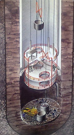
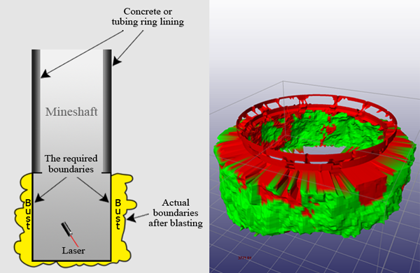
Traditional shaft sinking includes drilling and blasting operations at the shaft bottom followed by cleaning of loose material. The shaft may have some overbreak (over-blast) after blasting. The typical contractual allowance is 15cm in any radial direction, however if the surrounding rock is weak or fractured, excessive overbreak in inevitable. This results in extra ground to be hoisted and additional concrete to be poured costing both time and money. The amount of extra muck and concrete can be a contentious point between a sinking contractor and a client as the latter must pay extra for both.
The set of tools offered by Shaft Builder provides highly efficient and accurate methods to assess any additional mucking and concrete works required and is based on processing the data from a static 3D laser scanner installed at the shaft bottom. Scanning (for the section of the shaft up to 20m in height and 6-12m in diameter) occurs before pouring the concrete lining, or tubbing installation, and takes only about 3-5 minutes to complete. Thereafter the sinking operations can be resumed.
By integrating the processed scans with information contained in the mine shaft data base (rock support, lining design, surrounding geology and face mapping, engineering drawings, etc.), Shaft Builder delivers fast, accurate calculations of mined volumes and required amount of concrete. It also provides visualization, printing and organization of surveying documentation required by various regulating authorities.
Installation of permanent lining and elements for equipping mine shafts.
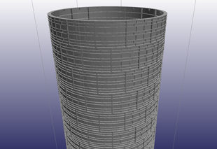
Most of works related to the installation of permanent concrete lining and elements required for subsequent shaft equipping, are carried out from the sinking stage. If using cast-iron tubbings as a permanent lining, the installation of tubbing rings is carried out from the shaft bottom face after completion of cleaning works. 3D static laser scanning of mine shaft walls is done from the top deck of the sinking stage, or from the shaft bottom, and offers an effective method of controlling the quality of lining installation. Shaft Builder processes and analyzes the scanned data allowing users to find explicit defects in concrete or tubbing lining (cracks, scaling, gaps between segments), check the geometric shape of lining (deviation from a proper cylinder or any other designed layout), and the actual position of nut-boxes, mounting brackets, rock-bolts, etc. It is assumed that during this stage of scanning, the main elements of shaft equipping, e.g., buntons and guides, are not installed.
Equipping the mine shaft
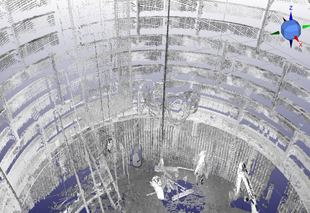
The final stage of mine shaft surveying is the capture of its internal infrastructure after installation of the main constructive elements (buntons and guides) and other engineering services (pipelines, electrical cables, ventilation ducts, etc.). This scan not only provides quality control of the installed construction elements, but also serves as a template for shaft inspections and monitoring during the operations.
Scanning should be carried out in such a manner as to avoid any blind spots to ensure a complete 3D model of the actual constructed mine shaft can be built.
Shaft Builder includes a module for point cloud integration and processing. Processing takes place in the surveyor’s office at the surface and the results can be kept in the integrated mine shaft database.


