Our solution for mine shaft inspection solution is designed to provide safe and more effective underground mining operations. Shaft Inspection, the software component, is used for post-processing of 3D laser scanning data collected by our Mine Shaft Scanning System (MS3) – a tool for the inspection, monitoring and profiling of mineshafts.
Shaft Inspector consists of the following key software components:
- Database of mine shaft constructive elements and scans (based on SQL Server or Oracle)
- Data accessing and data processing algorithms
- Data presentation and data visualization layer
Separation of components allows users to review, amend, change, or substitute parts of each module without affecting other modules. The logical connection between the modules facilitates an effective workflow for data processing.
Shaft Inspector involves the following stages of implementation:
1. Creation of a mineshaft constructive elements database
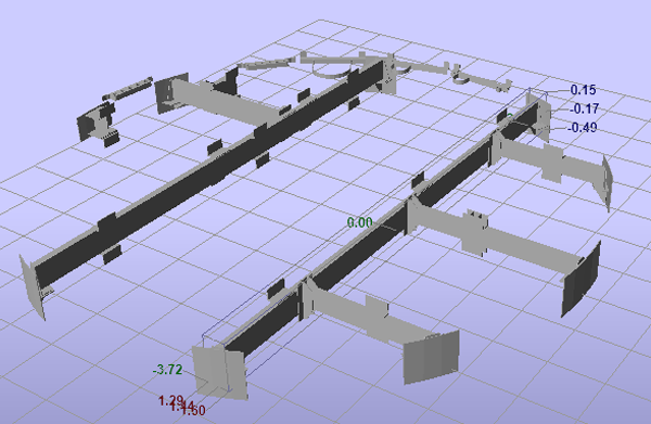
The constructive element database is the informational heart of the technology. It can be used either separately or in combination with MS3. The constructive element database assists technical personnel by providing a fast and convenient method for tracking all changes, construction, modifications, and repairs done inside of the mine shaft and/or to its headgear.
The mine shaft constructive element database can be created in two ways:
- From the existing drawings of the mine shaft (elevations, layouts, cross-sections, etc.) in any CAD format or,
- From the initial 3D laser scan, processed and optimized.
Both methods can be combined in for higher quality results. Semi-automated tools assist in creating the mine shaft constructive elements database.
2. MS3 device configuration
Each mine shaft is unique. The main challenge for the designers of MS3 is to configure the generic MS3 system for conditions in each mine shaft.
A mine shaft scanning simulation tool is used to provide a well-defined and consistent process. Using the initial mine shaft model, and setting up certain parameters (number of scanners, their speed and angle of scanning, orientation, etc.), the tool assists the designer in finding the optimal solution and appropriate MS3 configuration (no blind spots or minimum known blind spots, sufficient density of points vs. scanning speed, etc.).
3. Processing the initial scan and updating the initial model
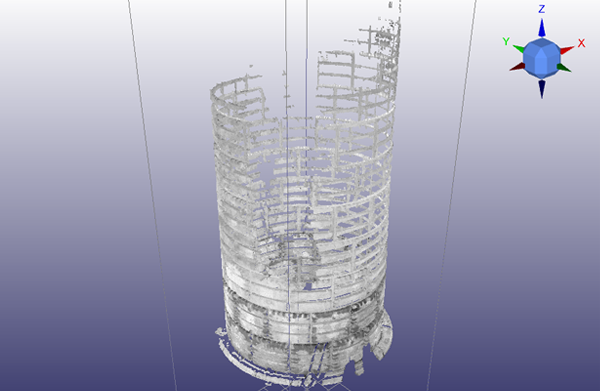
After assembling the device, it is necessary to perform an initial scan. The first real scan provides an opportunity to improve the accuracy of the mine shaft constructive elements database, update it with the newly installed elements, and amend the description of topology, metrical and other properties. This step also requires the definition of all deviation tolerances for sets of parameters that are subject to an inspection check.
- The mineshaft element database is reviewed considering the differences revealed between the preliminary “theoretical” description of elements and the initial “real” scanning results. The description of elements should reflect the actual status.
- This database is set up as a template for further automated inspections.
- A database of defects with permissible deviation tolerances and thresholds is generated.
4. Acquiring and analyzing regular inspection scans
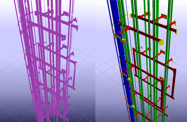
Mining laws, stipulated in nearly all countries with a mineral-extracting industry, state that mine shaft inspections must take place on a regular basis in accordance with certain schedules: daily, weekly, monthly, etc. This means that new scans will be captured and uploaded to the MS3 database regularly, following the predetermined schedule of inspections. Scanning can be also complemented by digital high resolution, colored photos or videos taken simultaneously.
As soon as the new scan becomes available Shaft Inspector begins the processing. The following logic is implemented:
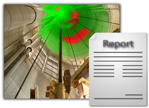
- Comparison of the last scan with both the template shaft model and a previous scan, is required to identify problematic areas including cracks in lining, misalignment of pipelines, buntons and guides, etc., and to visually highlight changes to all elements and zones.
- A report is generated containing the records for all identified differences.
- Using built-in algorithms, the engineer responsible for mine shaft operations generates a repair and maintenance order or a job card (to fix problems) based on report and visual analysis of the last scan and pictures.
- The template mine shaft model must be updated after completion of repairs to reflect their status and will be used as the new guideline.

